Defining Computational Fluid Dynamics (CFD) in Modern Engineering
What and Why CFD Simulation Matters in your next project? Computational Fluid Dynamics represents a virtual engineering methodology that enables you to predict fluid behaviour, thermal patterns, and pressure distribution within your systems before physical construction begins. You gain the ability to visualise airflow, heat transfer, and particle movement through digital simulations that mirror real-world physics. This technology transforms how you approach design challenges across HVAC systems, data centers, cleanrooms, and industrial facilities.
The Physics of Fluid Flow and Heat Transfer
Fluid dynamics governs how air and liquids move through your building systems, carrying thermal energy and affecting occupant comfort. You encounter these principles daily in ventilation systems, cooling equipment, and smoke control designs. CFD captures the complex interactions between velocity, temperature, pressure, and turbulence that determine system performance and energy consumption.
Mathematical Foundations: Navier-Stokes Equations Simplified
The Navier-Stokes equations form the mathematical backbone of fluid motion prediction, describing how velocity and pressure change throughout your system. You don’t need to solve these complex differential equations manually-CFD software handles the computational work. These equations account for fluid viscosity, momentum, and conservation laws that govern real-world behaviour.
Your CFD simulations rely on these equations to calculate millions of data points across your design geometry. The software divides your system into small computational cells, solving the Navier-Stokes equations at each location to predict flow patterns. You receive detailed results showing velocity vectors, temperature distributions, and pressure gradients that would be impossible to measure physically during the design phase. This mathematical approach allows you to test multiple design scenarios quickly, comparing performance metrics before committing to construction. The equations automatically account for turbulence, buoyancy effects, and heat transfer mechanisms that influence your system’s real-world operation.
The Evolution of CFD from Academic Research to Industry Standard
CFD technology began in aerospace research laboratories during the 1960s but remained computationally expensive for decades. You now have access to powerful simulation tools that were once exclusive to government agencies and large corporations. Modern computing power has made CFD accessible for building design, HVAC optimisation, and industrial applications.
Your engineering projects benefit from decades of software development that has refined numerical methods and user interfaces. Early CFD required specialised programming knowledge and supercomputers, limiting its practical application to high-stakes aerospace and defence projects. The 1990s brought commercial software packages with graphical interfaces, though simulation times still stretched across days or weeks. Cloud computing and parallel processing now deliver results within hours, making CFD practical for typical project timelines and budgets. Building codes and engineering standards increasingly reference CFD validation, particularly for smoke control systems, cleanroom certification, and energy performance verification. You can integrate simulation into your standard design workflow rather than treating it as an exceptional analysis reserved for problematic projects.

Why Traditional Design Methods May Not Be Enough
Your engineering projects today face complexities that conventional design approaches struggle to address adequately. Empirical formulas and simplified calculations were developed for standard conditions, but modern systems involve intricate geometries, multiple interacting variables, and performance requirements that exceed traditional method capabilities. Relying solely on these established techniques can leave you exposed to unexpected performance failures, compliance issues, and costly post-construction modifications that could have been prevented through simulation analysis.
The Limitations of Empirical Formulas in Complex Geometries
Standard engineering formulas work well for simple, textbook scenarios but fail when you introduce architectural complexity. Your data centre with irregular ceiling heights, multiple heat sources, and obstructed airflow paths cannot be accurately predicted using basic equations. CFD simulation captures the nuanced fluid behaviour that empirical methods simply cannot represent in non-standard configurations.
Risks Associated with Relying on Oversimplified Assumptions
Oversimplified design assumptions can lead you to underestimate pressure drops, misjudge temperature distributions, and miscalculate ventilation effectiveness. Your HVAC system might appear adequate on paper yet fail to maintain comfort conditions or meet air quality standards once installed. These gaps between predicted and actual performance expose your project to regulatory non-compliance and expensive remediation work.
Design teams often apply safety factors to compensate for uncertainty, but this approach frequently results in over-specification. You end up purchasing larger equipment, increasing energy consumption, and inflating capital costs without achieving proportional performance benefits. Smoke control systems designed with excessive margins may still fail during actual fire scenarios because simplified models cannot predict how smoke stratification, buoyancy effects, and pressure differentials interact in your specific building layout. CFD simulation eliminates guesswork by providing you with detailed visualisations of flow patterns, temperature profiles, and concentration distributions under various operating conditions, enabling optimised rather than over-engineered solutions.
The Inefficiency and High Cost of Physical Scale Testing
Physical prototypes and scale models require significant time and budget while offering limited flexibility for design iteration. Your testing setup captures only specific operating conditions, and modifying the design means building new models. CFD simulation allows you to evaluate dozens of design variations quickly, exploring performance across multiple scenarios without physical construction costs.
Wind tunnel testing for building aerodynamics or cleanroom validation through full-scale mock-ups can consume months of your project schedule and substantial financial resources. Each design modification necessitates repeating the entire testing process, creating bottlenecks that delay project delivery. Scale models introduce their own uncertainties through Reynolds number mismatches and measurement limitations that may not accurately represent full-scale behaviour. Your team faces difficult choices between thorough testing and meeting project deadlines. Virtual simulation provides you with comprehensive performance data across your entire operating envelope-from normal conditions to extreme scenarios-without the constraints of physical testing. You can assess thermal comfort, contamination control, fire safety, and energy efficiency simultaneously, identifying optimal solutions before committing resources to fabrication or construction.
Diagnostic Precision: Identifying Hidden Airflow and Thermal Issues
Your engineering project may harbour invisible performance problems that only become apparent after construction or installation. CFD simulation reveals these hidden issues by creating detailed visualisations of airflow patterns, temperature distributions, and thermal behaviour throughout your system. You gain the ability to diagnose problems before they materialise, saving substantial time and budget while ensuring your design meets performance specifications from day one.
Detecting Dead Zones, Recirculation, and Short-Circuiting
Stagnant air pockets and inefficient circulation patterns often escape detection during traditional design reviews. CFD analysis exposes these problematic zones by tracking particle trajectories and velocity vectors throughout your space. You can identify where supply air short-circuits directly to return grilles, where recirculation loops form, and where ventilation effectiveness drops below acceptable standards.
Mapping Temperature Gradients and Thermal Stratification
Temperature variations within your facility directly impact occupant comfort, equipment performance, and energy consumption. CFD simulation generates precise thermal maps showing hot spots, cold zones, and stratification layers that conventional calculations cannot predict. You receive quantifiable data on temperature distribution at every point in your system, enabling targeted design adjustments before implementation.
|
CFD Analysis Capability |
Engineering Value |
|
3D temperature field visualisation |
Identifies thermal comfort issues across occupied zones |
|
Stratification layer detection |
Optimises HVAC system placement and sizing |
|
Hot spot identification |
Prevents equipment overheating and failure |
|
Cold zone mapping |
Eliminates condensation risk areas |
Thermal stratification poses particular challenges in spaces with high ceilings, such as atriums, warehouses, and data centers. Your heating and cooling systems may work harder than necessary when warm air accumulates near the ceiling while occupied zones remain uncomfortably cool. CFD simulation quantifies the degree of stratification and tests various destratification strategies virtually. You can evaluate different diffuser types, supply air temperatures, and fan placement options to achieve uniform temperature distribution. The simulation shows exactly how thermal plumes rise from heat sources, where they spread, and how they interact with your ventilation system, giving you the information needed to optimise energy efficiency while maintaining comfort standards.
Predicting Moisture Control and Potential Condensation Points
Condensation problems lead to mould growth, material degradation, and indoor air quality issues that are expensive to remediate. CFD simulation predicts where moisture will accumulate by analysing surface temperatures, dewpoint conditions, and humidity distribution. You can identify condensation-prone surfaces and implement preventive measures during the design phase rather than addressing failures after occupancy.
|
Moisture Analysis Feature |
Risk Mitigation Benefit |
|
Surface temperature prediction |
Identifies surfaces below dewpoint temperature |
|
Humidity distribution mapping |
Locates high-moisture concentration zones |
|
Vapour pressure gradient analysis |
Predicts moisture migration pathways |
|
Condensation risk assessment |
Enables proactive insulation and ventilation design |
Your facility’s moisture control strategy requires understanding the complex interaction between airflow, temperature, and humidity levels. Cold surfaces such as uninsulated pipes, exterior walls, and chilled beams become condensation sites when humid air contacts them. CFD simulation calculates the exact surface temperatures throughout your space and compares them against local dewpoint conditions based on your ventilation rates and outdoor air intake.
Economic Advantages: Saving Time and Cost via Virtual Prototyping
Virtual prototyping through CFD simulation delivers measurable financial benefits to your engineering projects. You can test multiple design scenarios digitally, eliminating the need for expensive physical mockups at every iteration stage. Your project budget remains protected while you explore optimal solutions through computational analysis. CFD allows you to validate system performance before committing resources to fabrication or construction.
Accelerating the Design Cycle through Rapid Iteration
Digital testing enables you to evaluate dozens of design variations within days rather than weeks. Your engineering team can modify parameters, adjust configurations, and assess performance outcomes without waiting for physical prototypes. This speed advantage compresses your project timeline and allows you to respond quickly to design challenges or client requirements.
Minimising Material Waste and Physical Prototype Expenses
Physical prototypes consume raw materials, fabrication time, and labour costs for each iteration you test. CFD simulation eliminates most of these expenses by moving your testing phase into the digital environment. You preserve your material budget while achieving more comprehensive design validation than traditional methods allow.
Building physical prototypes for complex systems like HVAC installations, cleanroom designs, or industrial ventilation requires significant material investment. Each design modification demands new components, assembly time, and testing equipment. Your project incurs these costs repeatedly until you achieve satisfactory performance. CFD simulation reverses this expensive cycle by allowing you to perfect your design virtually before ordering a single component. You only build physical prototypes when your digital analysis confirms optimal performance, reducing material consumption by up to 70% in typical engineering projects. This approach also shortens procurement cycles since you order materials with confidence in their final application.
Preventing Expensive On-Site Remedial Works Post-Construction
Design flaws discovered after construction require costly retrofits, system modifications, and project delays. CFD simulation identifies performance issues during the design phase when changes cost a fraction of post-construction fixes. You avoid expensive rework by validating your engineering concepts before breaking ground or installing equipment.
On-site remedial work disrupts operations, extends project timelines, and multiplies your labour costs. Discovering that your HVAC system creates dead zones, your data centre cooling proves inadequate, or your smoke control fails compliance testing after installation forces you into expensive emergency solutions. Contractors must return, equipment may need replacement, and building occupancy gets delayed. These scenarios can inflate your project costs by 30-50% beyond the original budget. CFD simulation provides the foresight you need to avoid these situations entirely. Your team can visualise airflow patterns, temperature distributions, and pressure fields before construction begins, ensuring code compliance and performance targets are met the first time. This proactive approach protects your reputation, maintains client relationships, and keeps your projects profitable.
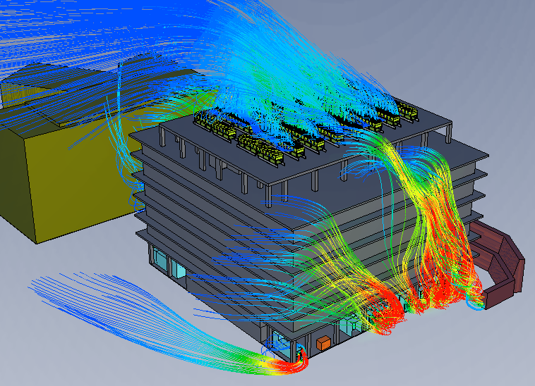
Application Focus: HVAC Systems and Data Centre Management
CFD simulation transforms how you approach climate control in commercial buildings and mission-critical facilities. Your HVAC systems and data centre cooling strategies benefit from detailed airflow visualisation that reveals temperature stratification, dead zones, and pressure imbalances before construction begins. You can test multiple design scenarios virtually, comparing equipment configurations and duct layouts to identify the most energy-efficient solution for your specific space requirements.
Enhancing Occupant Comfort in Large Atriums and Open Spaces
Large volume spaces present unique thermal challenges that traditional design methods struggle to predict accurately. CFD analysis shows you exactly how air circulates through your atrium, identifying cold drafts near glazing and hot spots under skylights. You can optimise diffuser placement and supply temperatures to maintain consistent comfort levels throughout the occupied zone.
Optimising CRAC Unit Placement and Cold/Hot Aisle Containment
Data centre efficiency depends on strategic cooling equipment positioning and proper airflow containment. CFD simulation reveals bypass airflow, recirculation patterns, and temperature hotspots that compromise your server performance. You can evaluate CRAC unit quantities and locations to achieve uniform cooling distribution while minimising energy consumption.
Your containment strategy requires careful analysis of pressure differentials and airflow paths to prevent hot air mixing with cold supply air. CFD modelling allows you to test various containment configurations-from physical barriers to blanking panels-and quantify their impact on cooling effectiveness. You’ll see precisely how air moves around cable trays, under raised floors, and through perforated tiles, enabling you to fine-tune your design for maximum thermal efficiency. The simulation identifies which server racks receive inadequate cooling and where you’re over-cooling, helping you balance your infrastructure investment with operational performance requirements.
Managing High-Density Cooling Requirements in Critical Infrastructure
High-performance computing clusters and dense server deployments generate heat loads exceeding 20kW per rack, demanding sophisticated cooling approaches. Your CFD analysis predicts equipment inlet temperatures under peak load conditions, validating whether your cooling infrastructure can handle future capacity expansion. You can assess supplemental cooling technologies like rear-door heat exchangers before committing to capital expenditure.
Critical facilities cannot afford thermal failures that trigger emergency shutdowns or damage expensive equipment. CFD simulation lets you model failure scenarios-such as CRAC unit outages or blocked airflow paths-to understand how quickly temperatures rise and which racks face the greatest risk. You can design redundancy into your cooling system based on quantified performance data rather than conservative rules of thumb. The analysis also helps you evaluate liquid cooling integration, showing how in-row coolers or direct-to-chip systems interact with your existing air-based infrastructure to maintain safe operating temperatures across all equipment zones.
Innovation Catalyst: CFD in Advanced Product Development
CFD simulation accelerates your product development cycle by enabling virtual testing of multiple design concepts before committing to physical prototypes. You can explore unconventional geometries, test extreme operating conditions, and validate performance claims without the expense of building test units. This computational approach transforms how you develop products, allowing your engineering team to make data-driven decisions that balance performance, cost, and manufacturability from the earliest design stages.
- Virtual prototyping reduces physical testing requirements by up to 70%
- Design optimisation occurs in days rather than weeks or months
- Performance validation happens before tooling investment
- Multiple operating scenarios can be evaluated simultaneously
- Design modifications are implemented at minimal cost
|
Traditional Development |
CFD-Enhanced Development |
|
Multiple physical prototypes required |
Virtual iterations before prototype |
|
Limited testing scenarios |
Unlimited virtual test conditions |
|
High iteration costs |
Low-cost design modifications |
|
Extended development timelines |
Compressed time-to-market |
|
Performance issues found late |
Early problem identification |
Aerodynamic Refinement of Mechanical and Industrial Components
Your mechanical components often operate in complex flow environments where drag, lift, and pressure distribution directly impact performance and efficiency. CFD simulation reveals how air interacts with surfaces, identifying flow separation zones, recirculation patterns, and pressure losses that compromise your design. You gain quantitative data on aerodynamic forces, allowing your team to refine component geometry for reduced resistance and improved operational efficiency.
Thermal Analysis of Electronic Enclosures and Circuitry
Electronic systems generate substantial heat that must be managed to prevent component failure and ensure reliable operation. CFD simulation maps temperature distribution across your circuit boards, identifies hotspots, and evaluates cooling strategies before you manufacture enclosures. Your design team can optimise ventilation openings, heat sink placement, and airflow paths to maintain safe operating temperatures throughout the product lifecycle.
Heat-related failures account for over 55% of electronic product malfunctions, making thermal management a critical design consideration. CFD simulation provides you with detailed temperature profiles showing exactly where thermal issues will occur under various operating loads. You can evaluate natural convection, forced air cooling, or liquid cooling strategies within the same virtual model. The simulation accounts for component power dissipation, material thermal properties, and ambient conditions to predict real-world thermal behaviour. Your engineering team receives visual temperature maps and quantitative data showing whether components will operate within manufacturer-specified temperature ranges. This analysis extends product lifespan, improves reliability, and reduces warranty claims by ensuring adequate thermal management from initial design through production.
Leveraging Parametric Studies for Optimised Product Performance
Parametric analysis through CFD allows you to systematically vary design parameters and quantify their impact on product performance. Your team can evaluate dozens of geometric variations, material selections, or operating conditions within a structured simulation framework. This methodical approach identifies the optimal combination of design variables that maximise performance while meeting cost and manufacturing constraints.
Design optimisation traditionally relies on intuition and limited experimental data, often resulting in suboptimal solutions that leave performance gains unexplored. Parametric CFD studies automate the evaluation of design alternatives by systematically varying parameters such as inlet sizes, component spacing, surface geometry, or flow rates. You define the parameter ranges of interest, and the simulation software generates performance data across the entire design space. The results reveal not just which design performs best, but how sensitive performance is to each parameter. Your team discovers unexpected interactions between design variables that manual testing would likely miss. This comprehensive understanding enables you to make informed trade-offs between competing objectives such as efficiency, cost, size, and manufacturability.
Strategic Timing: When Should CFD Simulation Be Conducted?
Timing your CFD simulation correctly can determine whether you prevent problems or merely diagnose them after they occur. You should consider simulation at three key project stages: during initial conceptual design, when troubleshooting operational issues, and before implementing retrofits or expansions. Each phase offers distinct advantages that directly impact your project’s technical success and budget performance.
The Benefits of Integration During the Conceptual Design Phase
Early-stage CFD analysis allows you to test multiple design concepts virtually before committing to expensive equipment purchases or construction. You can compare different system configurations, optimise component sizing, and identify potential performance bottlenecks when design changes cost the least to implement.
Troubleshooting Existing Systems and Performance Auditing
Operational facilities experiencing temperature inconsistencies, inadequate ventilation, or energy inefficiencies benefit from CFD-based performance audits. You can pinpoint the root causes of system underperformance without invasive testing or costly trial-and-error modifications to existing infrastructure.
CFD simulation transforms troubleshooting from guesswork into data-driven problem-solving. When your facility experiences comfort complaints, contamination issues, or equipment overheating, simulation recreates actual operating conditions to reveal hidden airflow patterns, thermal stratification, or pressure imbalances. You gain visual evidence of how air moves through your space, where dead zones exist, and which modifications will deliver measurable improvements. This approach saves you from implementing ineffective solutions while providing stakeholders with clear justification for recommended system upgrades or operational adjustments.
Re-Validating Designs During Building Retrofits and Expansions
Renovation projects introduce new equipment, altered layouts, or changed occupancy patterns that affect your existing environmental control systems. CFD simulation verifies whether your current HVAC infrastructure can accommodate these changes or requires upgrades to maintain performance standards and code compliance.
Building modifications rarely occur in isolation-your new server rack, additional production equipment, or reconfigured workspace can create unforeseen interactions with existing systems. CFD analysis models these complex scenarios before construction begins, revealing whether your current mechanical systems have sufficient capacity or require supplemental equipment. You can evaluate multiple retrofit scenarios to find the most cost-effective solution that meets your performance objectives. This validation process protects your investment by ensuring that expansion plans won’t compromise environmental conditions, safety compliance, or operational efficiency in adjacent areas that remain unchanged.
Choosing The Right CFD Partner: Why Megagenix
Selecting a qualified CFD partner can determine whether your engineering project achieves optimal performance or faces costly redesigns. You need a simulation provider who combines deep technical knowledge with proven industry experience to deliver results that translate directly into actionable design improvements. Megagenix brings specialised expertise across HVAC systems, data centre cooling, cleanroom environments, fire safety, and thermal management applications, ensuring your project benefits from domain-specific insights that generic consultants cannot provide.
Assessing Technical Expertise and Domain Knowledge
Your CFD partner must demonstrate proven experience in your specific industry sector to deliver meaningful simulation results. Megagenix engineers possess specialised knowledge across building services, industrial ventilation, electronic cooling, and aerodynamic applications, enabling accurate modelling of complex fluid dynamics scenarios. This domain expertise ensures that simulation assumptions, boundary conditions, and validation methods align with real-world engineering standards and performance expectations.
The Importance of Advanced Computing Power and Rigorous Validation
Accurate CFD analysis demands substantial computational resources and strict validation protocols to ensure simulation reliability. Your project deserves results backed by high-performance computing infrastructure and verification against established benchmarks, experimental data, and industry best practices. Megagenix employs advanced meshing techniques and solver technologies that capture complex flow phenomena while maintaining computational efficiency.
High-quality CFD simulation requires systematic validation approaches that confirm your results reflect physical reality. Professional CFD providers implement multiple verification stages, comparing simulation outputs against analytical solutions, published experimental data, and field measurements when available. This rigorous quality assurance process protects you from design decisions based on inaccurate predictions that could compromise system performance or safety compliance.
- Grid independence studies to ensure mesh resolution adequacy
- Turbulence model selection based on flow regime characteristics
- Boundary condition verification against design specifications
- Convergence monitoring to confirm solution stability
- Post-processing validation using engineering judgment and physical principles
|
Validation Method |
Application Benefit |
|
Benchmark comparison |
Confirms solver accuracy against known solutions |
|
Experimental correlation |
Validates model predictions with measured data |
|
Code verification |
Ensures proper implementation of governing equations |
|
Sensitivity analysis |
Identifies critical parameters affecting results |
|
Physical reasoning |
Applies engineering judgment to assess result plausibility |
Delivering Actionable Insights and Tailored Engineering Solutions
Raw simulation data holds limited value unless translated into clear design recommendations you can implement immediately. Megagenix transforms complex CFD results into practical engineering guidance, identifying specific modifications that optimise system performance, reduce energy consumption, or resolve compliance issues. Your project receives comprehensive reports with visualisations, quantitative metrics, and prioritised recommendations that support confident decision-making throughout design development.
Effective CFD consulting extends beyond generating colourful flow visualisations to providing engineering solutions tailored to your project constraints and objectives. You benefit most when your CFD partner understands budget limitations, schedule pressures, and performance targets that shape design decisions. Megagenix collaborates with your project team to explore multiple design scenarios, quantify performance trade-offs, and recommend cost-effective solutions that meet technical requirements without unnecessary over-design. This consultative approach ensures simulation insights integrate seamlessly into your engineering workflow, accelerating design iterations while reducing project risk and avoiding expensive construction-phase modifications.
Final Words
Following this exploration of CFD simulation benefits, you now understand how this technology transforms your engineering projects from concept to reality. Megagenix delivers precise computational analysis that saves you time and money while ensuring your systems perform optimally. Your projects deserve the confidence that comes from validated designs, reduced risk, and data-driven decisions. Partnering with experienced CFD specialists gives you the competitive advantage needed in today’s demanding engineering environment. Contact here.
FAQ
Q: What is CFD simulation and how does it work in engineering projects?
A: CFD (Computational Fluid Dynamics) simulation is a digital engineering tool that predicts how air, fluids, heat, and particles move through spaces and systems. The software divides your design into millions of small cells, then calculates physical properties like velocity, temperature, and pressure at each point. Engineers use these results to visualise airflow patterns, identify hot spots, detect areas of poor ventilation, and optimise system performance.
For a data centre project, CFD shows exactly where cooling air flows and where heat accumulates around server racks. For an HVAC design, it reveals whether conditioned air reaches all occupied zones effectively. The simulation runs on mathematical equations that govern fluid mechanics and heat transfer, producing detailed reports and visual animations that help project teams make informed design decisions before spending money on physical construction or prototypes.
Q: At what stage should we integrate CFD analysis into our project timeline?
A: The best time to start CFD analysis is during the early design development phase, typically after initial concepts are established but before detailed engineering drawings are finalised. Early integration allows your team to test multiple design options quickly and cost-effectively. You can compare different HVAC layouts, adjust duct sizes, relocate equipment, or modify room configurations without demolition or material waste.
Many projects benefit from CFD at the schematic design stage when 30-40% of design decisions are made. For complex facilities like cleanrooms, laboratories, or mission-critical data centres, even earlier involvement during conceptual design proves valuable. Late-stage CFD analysis still provides benefits for troubleshooting problems or validating final designs, but design changes become exponentially more expensive after construction documents are issued or equipment is ordered. Budget 2-4 weeks for initial CFD studies and plan for iterative analysis as your design evolves through different project phases.
Q: How does CFD simulation reduce costs compared to traditional design methods?
A: CFD simulation identifies design problems in the virtual environment where fixes cost only engineering time, not construction materials and labour. Traditional trial-and-error approaches often require physical mockups, on-site modifications, or post-construction remediation that can cost 10-50 times more than simulation-based optimisation. A pharmaceutical cleanroom project might need expensive HEPA filters and air handling units sized 30% larger than necessary without CFD validation, wasting hundreds of thousands in capital and ongoing energy costs.
Data centre operators who skip CFD analysis frequently discover hot spots after go-live, forcing emergency equipment additions or operational restrictions. The simulation also reduces commissioning time by ensuring systems perform correctly from startup. Testing five different ventilation strategies in CFD costs roughly the same as analysing one design, but building and testing five physical options would be prohibitively expensive. Project teams typically see 5:1 to 20:1 return on investment from CFD analysis through avoided redesigns, optimised equipment sizing, and improved energy efficiency over the building’s operational life.
Q: What specific engineering problems can CFD simulation solve for our facility?
A: CFD addresses any challenge involving air movement, temperature control, or contaminant management in your facility. For HVAC systems, it determines optimal diffuser locations, identifies dead zones with poor air circulation, and verifies that temperature gradients meet comfort standards. In industrial settings, CFD maps how dust, fumes, or chemical vapours disperse and whether exhaust systems capture contaminants effectively before reaching workers.
Fire safety engineers use CFD to model smoke movement during emergencies, ensuring evacuation routes remain tenable and smoke control systems perform as designed. Cleanroom and laboratory projects require CFD to demonstrate ISO classification compliance and validate that airflow patterns prevent cross-contamination. Data centre managers rely on CFD to eliminate hot spots, optimise cold aisle containment, and plan capacity expansions without over-cooling. Building owners use CFD to diagnose comfort complaints, reduce energy consumption, or evaluate how architectural features like atriums and facades affect indoor climate. The simulation also tests extreme scenarios-equipment failures, high-occupancy events, or unusual weather conditions-that would be dangerous or impractical to evaluate in real facilities.
Q: How do we interpret CFD results and apply them to our project decisions?
A: Interpreting CFD results involves analysing visual animations, contour plots, and quantitative data to translate complex simulations into actionable engineering decisions. You can apply these results by using visual tools to identify hidden performance issues like dead zones or thermal stratification, validating design performance against specific regulatory or comfort requirements, and testing “what-if” failure scenarios to build system redundancy. Furthermore, you can use these results for parametric optimisation—systematically varying design inputs to find cost-effective solutions—and to support data-driven decision-making by quantifying trade-offs between competing project objectives like energy efficiency, cost, and capacity.