Skip to content

FEA Simulation Sample for Roofing Structure

Summary

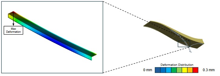
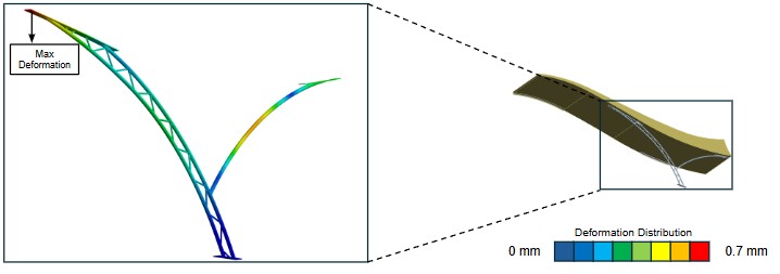
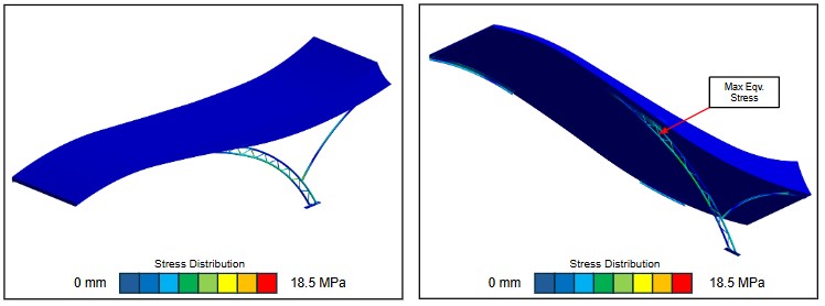
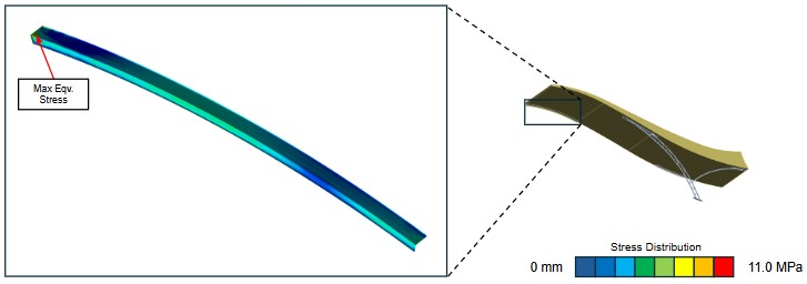
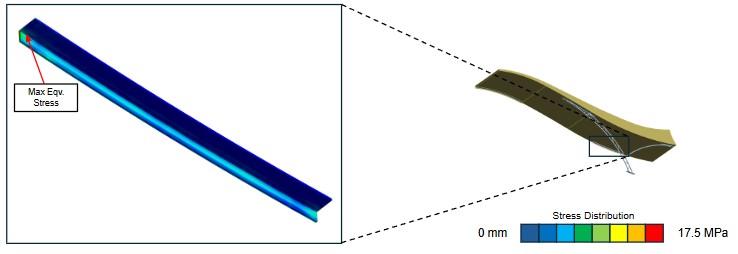
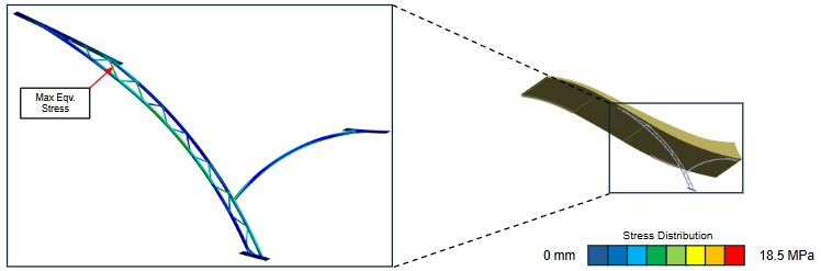
This study presents a comprehensive numerical evaluation of a proposed roofing/awning structure using Finite Element Analysis (FEA). It assessed the structural integrity of the system under governing load cases, providing detailed insights into deformation, stress distribution, and overall structural safety.

Introduction

Using FEA, the total deformation across the roof, front bracket, rear bracket, and truss structure were evaluated, highlighting areas of maximum displacement and critical stress points. These insights were used to determine whether the roof can safely withstand applied loads while maintaining structural integrity and reliability.

Objectives

FEA was performed to verify that the stresses and deflections remain within allowable limits and that the structure can safely withstand the applied loads.

Scope of Work

The analysis considered:

  • Self-weight of structural members
  • Material properties and connection behavior
  • Support and boundary conditions

Methodology

Roof Construction

A detailed digital model of the roof was created, incorporating the truss structure, roofing material, bracket material, and precise measurements to accurately represent the physical system.

Load & Boundary Conditions

The simulation was set up with defined loads and boundary conditions to reflect the roof’s actual operating environment, ensuring accurate analysis of structural behaviour under the governing load cases.

Total Deformation

The total deformation of the roof illustrated the displacement response of the roofing/awning structure under the governing load case. The results indicated that maximum deformation occurs at the mid-span, farthest from any designated support points. 

  • Maximum Deformation: 1.61 mm

Supports Deformation

Front Bracket

The total deformation contour of the front bracket showed the displacement response under the governing load. Maximum deformation occurred near the mid-side of the roof area, close to the roof’s highest deformation spot.

  • Maximum Deformation: 0.27 mm

Rear Bracket

The rear bracket’s total deformation contour indicated maximum displacement near the mid-side of the roof area, which was consistent with the roof’s peak deformation.

  • Maximum Deformation: 0.22 mm

Truss Structure:

The truss structure experienced maximum deformation near the mid-side of the roof.

  • Maximum Deformation: 0.69 mm

Total Equivalent Stress

The total equivalent stress contour presented the equivalent stress response under the governing load case. Maximum stress occurred in chord members and selected diagonal members.

  • Maximum Equivalent Stress: 18.49 MPa

Supports Deformation Maximum Equivalent Stress

Front Bracket

Stress peaks occurred at the inner corners due to geometric discontinuities, causing local stress concentration.

  • Maximum Equivalent Stress: 10.72 MPa

Rear Bracket

Peak stresses were observed at inner corners of the bracket, where geometric discontinuities induced local stress concentrations.

  • Maximum Equivalent Stress: 17.11 MPa

Truss Structure

The truss structure experienced peak stress in chord members and selected diagonal members under governing load combinations.

  • Maximum Equivalent Stress: 18.49 MPa

Structural Analysis Results

The following table summarizes the structural safety evaluation based on maximum von Mises stress and SS 304 yield strength:

Stress Analysis Results
Name Material Max Eqv. Stress (MPa) Factor of Safety
Front Bracket 304 Stainless Steel (Yield Strength: 215 MPa) 10.72 20.1
Rear Bracket 17.11 12.6
Truss Structure 18.49 11.6

All components exhibited factors of safety significantly higher than typical code requirements. The minimum factor of safety exceeds 10, confirming that the structure is not stress-critical under the assessed load cases.

Conclusion

CFD transforms data center cooling from reactive troubleshooting to predictive, proactive design. By simulating airflow, temperature, and pressure distribution, engineers can identify risks early, optimize cooling strategies, validate designs, and support energy-efficient operations.

Accurate modeling and clear analysis ensure safer, more reliable, and sustainable data center environments, well before physical implementation. For future projects, CFD remains an essential step to optimize performance, reduce energy costs, and maintain operational resilience.